Horizontal hydraulic fracturing
Horizontal hydraulic fracturing, or "fracking", is a method used to increase the output of oil and natural gas wells and exploit tight hydrocarbon rich source rocks that do not naturally produce free-flowing oil or gas. It supplements a conventional vertically-drilled well hole with two relatively new techniques: horizontal drilling in the hydrocarbon-rich layer, and fracturing of the rock by the injection of fluids into the well at very high pressure. These measures greatly increase the effective contact area of the well with the petroleum-bearing rock, the result being an increased rate of flow of gas or oil out of the rock and into the hole. The technique has opened up the possibility of exploiting vast regions of the earth's crust formerly considered not viable as oil or natural gas sources because although they contained petroleum, it was too tightly bound within the rock to be accessible by conventional means.
Contents
Potential problems
Fracking is controversial for several reasons:
- The use of such a large new fund of fossil fuels will significantly increase greenhouse gasses (GHGs) and climate change;
- It will result in the industrialisation of presently non-industrialised regions (eg., residential, agricultural, wilderness areas) as they are turned into wellfields. All petreoleum wells, whether "fracked" or not, present issues of:
- air pollution from release of well contents;
- ground and groundwater pollution from drilling fluids;
- ground and groundwater pollution from well contents (petroleum, brine, etc.);[2]
- disturbance of water table;
- issues of general industrialisation:
- vehicle traffic
- intensive road construction
- introduction of pipelines into area
- in addition to the environmental costs of conventional drilling, hydraulic fracturing uses large quantities of water, which may deplete local water resources. And once used, the water is toxic and presents a large disposal problem.
- The idea of breaking up (fracturing) the very rock which they stand on may be repugnant to many people, irrespective of specific pollution or resource-related concerns.
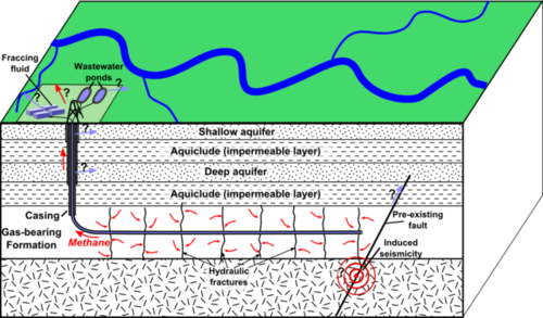
- Earthquake
 s, usually small, may result as faults develop or are augmented in underlying strata. This may occur even if fracking is not used, simply from extraction of oil or gas[3] or injection of waste water.[4] (They also think the injection of water may lubricate the fault and promote slippage.)
Overview
Nomenclature
Petroleum is a term used in the industry to encompass oil and natural gas.
Fluid. Anything that will flow. Encompasses liquids and gasses.
Permeability. The ability of a solid (eg., rock) to allow fluids to pass through itself. Requires both that the solid contain empty spaces (porosity) and that the spaces be connected. Permeability is abbreviated k, and measured in darcies (d). Horizontal hydraulic fracturing is used in rock whose permeability is too low for conventional production methods.
Filter cake. The residue left behind when a fluid in which solid particles are suspended (eg., fracking fluid or drilling mud) passes from the well hole into permeable rock. By clogging the rock pores it reduces fluid loss when fracturing, but also reduces petroleum flow back out of the rock.
In horizontal hydraulic fracturing, the wellbore, after having been drilled vertically for some distance (typically between a few hundred and a few thousand metres) is turned ninety degrees so that it then proceeds horizontally in the oil- or gas-rich layer, usually for another few thousand metres. This greatly increases the length of hole which is in contact with hydrocarbon-rich rock. Secondly, the horizontal section is "stimulated" by the injection of a liquid mixture of water and sand, called fracking fluid, at very high pressure (4,000-10,000 p.s.i., 30-70 MPa, typical) to make cracks in the rock, emanating out from the bore hole. These cracks represent a further increase in the contact area between the wellbore and the oil- or gas-bearing rock. The most common fracking mixture consists of water (75 to 98 per cent[5]), a "proppant", such as sand, and a cocktail of chemicals whose purpose is, among other things, to reduce friction, inhibit bacteria, and increase the viscosity of the fracking fluid. A viscosity higher than that of plain water is usually desirable in order to reduce the amount of fracking fluid lost into the formation, and to help with transport of the proppant. The function of the proppant is to get into the cracks and hold them open after the pressure has been released. Sand is the cheapest and most common proppant, but other materials such as bauxite, resin-coated sand, or ceramic beads, compact less when squeezed and are therefore less obstructive to petroleum flow in the fractures.[6]
The target rocks are sedimentary, often shale or sandstone, and often laid down in the Devonian or carboniferous periods, 300-400 million years ago. (To put this in perspective, the earth is about 5 billion years old; our species, homon sapiens, appeared about 200 thousand years ago and has been practising agriculture for about 20 thousand years. Many changes have occurred since the Devonian period, a time when North America straddled the equator, was connected to Europe, and was separated from South America by 3000 miles of water.)
The oil and natural gas derive from organic material, called kerogen, which was deposited along with the mineral component of silt, sand, gravel, etc., when the sediments which later became the rock accumulated. In rocks currently exploited for oil or gas, the kerogen is typically three to twenty per cent of total, by weight.[7] The kerogen, initially mostly macerated plant matter, or marine algae and phytoplankton, decomposes through two stages, biogenic degradation and thermal maturation, to become oil or natural gas. Older deposits tend to contain a higher proportion of natural gas, less oil.
Conversion factors
One barrel (abbreviated bbl.) = 42 US gal = 5.61 ft³ = 0.159 m³
One US gal. = 3.785 litre (l)
One pound per square inch (p.s.i.) = 6.894 kPa
Since the rock is sedimentary, it has a layered composition. The plane in which the layers are layed down is called the bedding plane. Initially horizontal or nearly so, over the millenia it becomes bent and heaved at various angles. When rock is hydrofracked, "the thin layers break with an irregular curving fracture parallell to the bedding plane."[8]
Hydraulic fracturing of vertical wells was first done in 1947,[9] and horizontal drilling has been done since the 1930s, but the use of the two techniques together only became commercially important in the late 1980s.(eg. in the Barnett shale, US).[10] Starting around - prior to hydraulic fracturing - wells were stimulated with explosives.[11]
Horizontally hydraulically fractured wells typically produce for 15-20 years[12] They are commonly re-fracked during this period to restore a falling output rate. Older natural gas wells often produced for 30-70 years.[13]
Reserves
Horizontal hydraulic fracturing is used in the following types of reserves:
- Tight oil. Oil imbedded in low permeability sandstone, carbonate, and shale rock (US EIA definition).[14] (It is estimated that tight oil will be 51% of the total onshore oil production of the lower 48 US states in.)[15]
- Tight gas. Natural gas from low-permeability sandstones and carbonate reservoirs. The gas is sourced (formed) outside the reservoir and migrates into the reservoir over time (millions of years). "Many of these wells are drilled horizontally and most are hydraulically fractured to enhance production."[16] Reservoir permeability is usually less than 100 microdarcies.[17]
- Shale gas. Natural gas from low permeability shale formations that are also the source for the gas.[18] The natural gas can be stored as free gas in natural fractures in the shale, as free gas in the micropores of the shale, or as adsorbed gas on the surfaces of the mineral or organic particles of the shale. Wells may be drilled either vertically or horizontally and most are hydraulically fractured to stimulate production.
The amount of petroleum in the ground can be expressed in various terms which are not at all equivalent. The most liberal estimates are original oil-in-place (OOIP) and original gas-in-place (OGIP). These express the total petroleum in reserves that are known to exist or appear likely to exist because of geological similarity with known petroleum-bearing regions. They are often calculated by estimating the volume of the reservoir (area x thickness) and multiplying that by the concentration of petroleum in the rock; so for example, a reservoir one square kilometre in area and ten metres thick, containing 5% oil by volume, would have an OOIP of 1000m x 1000m x 10m x 5% = 500,000m³ (about 3 million barrels). The word "original" indicates amounts in place prior to human intervention; presently remaining amounts are called just plain oil-in-place or gas-in-place. Only a fraction of petroleum resources-in-place are ever likely to be obtained by humans.
Technically recoverable resources (TRR) are the amount of petroleum thought likely to be obtained in the forseeable future.[19] They are less than resources-in-place because (a) not all fields are likely to be developed (because of sparseness of resource, technical obstacles, political obstacles, etc.); and (b) even in developed fields, only a fraction of the petroleum can be extracted - this is known as the recovery rate: for conventional oil it is typically about a quarter; for conventional natural gas, about three quarters; for shale gas with horizontal hydraulic fracturing, about one fifth.[20] Technically recoverable resource estimates are utterly dependent on levels of technology and on price. If the price of oil goes up (or the expected future price goes up) the TRR for oil goes up because it can be expected that previously unnattractive oil provinces will be brought under development, and those already under development will be exploited with more expensive techniques to squeeze out higher yields. Likewise, technical innovations that cause more complete, or faster, expliotation of the resource increase TRR. The magnitude of these effects is illustrated in the case of the Permian basin of Texas and New Mexico, USA, which prior to had a natural gas TRR of 5.2 trillion cubic feet (tcf), but after that year had a TRR of 41 tcf because shale gas plays there became considered exploitable.[21] According to the U.S. EIA, most increases in TRR are due, not to new petroleum discoveries, but to expectations that fields already under production will be exploited more completely.[22]
Proved reserves is the most conservative estimate of petroleum in the ground. It is the volume obtainable with reasonable certainty (often taken to be 90% certainty) from known reservoirs, under existing (not expected future) economic, technical and regulatory conditions. Like TRR, proved reserves varies more because of changing assessments of established fields than because of discoveries of new fields.[23]
Tight oil resources
BP estimates that the technically recoverable tight oil in the world is 240 billion barrels. They estimate that the North American share of that is 70 billion bbl., and the Asian share, 50 billion bbl.[24] However, the estimate seems low with the Bazhenov Formation![]() , 80 times the size of the Bakken formation
, 80 times the size of the Bakken formation![]() , in the Western Siberian Basin alone having
recoverable reserves estimated at 2 trillion barrels by some authors[25]
and at between 180 and 360 billion barrels by the national subsoil agency Rosnedra.[26]
Cumulative extraction of conventional crude oil by humans, up to the end of was about 1.1 trillion barrels. About 1.8 trillion barrels remain as conventional recoverable resource, according to Moujahed Al-Husseini, (includes 152 billion barrels in Canadian oil sands).[27]
, in the Western Siberian Basin alone having
recoverable reserves estimated at 2 trillion barrels by some authors[25]
and at between 180 and 360 billion barrels by the national subsoil agency Rosnedra.[26]
Cumulative extraction of conventional crude oil by humans, up to the end of was about 1.1 trillion barrels. About 1.8 trillion barrels remain as conventional recoverable resource, according to Moujahed Al-Husseini, (includes 152 billion barrels in Canadian oil sands).[27]
Tight gas resources
Aguilera et al. say the technically recoverable resources of tight gas in the U.S. lower 48 states and Canada, not including potentially large reserves in Quebec and the Canadian Maritimes, is 455 trillion cubic feet (tcf). It is contained in 15 petroleum provinces, whose convntional natural gas TRR is of similar size: 474 tcf. Based on analyses by others, eg. A Salvador and H Rogner (1996), who indicate that tight gas resources are present in almost all of the 937 petroleum provinces in the world, and the fact that tight gas resources roughly equal conventional gas resources in the places that Aguilera et al. have studied, the latter authors conclude that world tight gas TRR is potentially about equal to the world conventional gas TRR, which they cite as 15,100 tcf.
Shale gas resources
The following table shows estimates published in of technically recoverable shale gas.
| Region | Quantity |
|---|---|
| (tcf.) | |
| Australia | 396¹ |
| Algeria | 231¹ |
| Libya | 290¹ |
| South Africa | 485¹ |
| Argentina | 774¹ |
| Brazil | 226¹ |
| China | 1275¹ |
| India | 63¹ |
| Canada | 388¹ |
| Mexico | 681¹ |
| United States | 862¹ |
| France | 180¹ |
| Poland | 187¹ |
Table footnote:
1. U.S. EIA, World Shale Gas Resources.
The total technically recoverable shale gas in a group of 32 countries reviewed by the US Energy Information Administration (EIA) was 6,622 trillion cubic feet (tcf). The results for some of the more important of these countries are shown in the table. Russia and the Middle East countries were omitted from the survey even though they have significant shale gas reserves, the reason being that they also have large conventional natural gas reserves and thus probably less-than-usual incentive to pursue their shale gas. Undersea shale gas reserves were also omitted from the review, as were those for which there was too little information. According to the EIA, as of world total recoverable natural gas, exclusive of shale gas, is 16,000 tcf. Thus the 6,622 tcf of shale gas represents a 40% increase in the gas resource.[28]
Carbon
| Per gram burned | |||
| Fuel | Energy released | Carbon released in CO2 1 | Energy per gram carbon released 2 |
|---|---|---|---|
| kJ | grams | kJ | |
| Pure methane | 55.6 3 | 0.75 4 | 74.13 |
| Natural gas (mol. wt. 18; 90% methane) | 54.7 3 | 0.76 4 | 72.0 |
| Crude oil | 43 5 | 0.83 6 | 51.8 |
| Coal | 29 7 | 0.69 8 | 42 |
Table notes:
1. The carbon is released as a constituent of CO2. The masses in the table are for the carbon constituent only. For CO2 masses, multiply these values by 11/3.
2. Calculated from columns 2 and 3.
3. From heats of combustion in CRC Handbook.
4. From molecular weights.
5. Based on data in Skinner (appendix) and Smil, p 139.
6. Based on CO2 release data in Alexander et al. and heating values from Skinner and Smil.
7. A middle range value. Values vary from 26 for low quality lignites to 37 for best anthracite. Skinner; Encyclopedia Brittannica, "Fuels"; and Smil.
8. Alexander et. al., and heating values at left.
World situation
Based on the data in the above table, using
- A trillion barrels of oil will release 5,934 Exajoules and 114 petagrams carbon.
- 10,000 tcf of natural gas will release 11,800 Exajoules and 164 petagrams carbon.
- A trillion tons of coal will release 28,000 Exajoules and 690 petagrams carbon.
Fracturing
A horizontal well is usually not fractured all at once, but in sections, because of the difficulty of keeping the pressure up over the entire horizontal bore, which may be several kilometres long. Alexander et al. say division of the job into 10 to 20 sections is typical. They give the amount of water required for the whole job (total of all sections) as 10-20 million litres (3-5 million gallons). Other authors give figures ranging from 8-60 M litres (2-16 M gal.).[29]
Fractures can extend feet vertically:
Kevin Fisher, an engineer who works for Pinnacle Technologies, a Halliburton Service firm, examined thousands of fractures in horizontal wells in the Barnett and Marcellus Shale formations, using microseismic monitoring equipment to measure their extent. Fisher found that the most extreme fractures in the Marcellus Shale were nearly 2,000 feet in vertical length.[30]
Fracturing-fluid additives may include: acids, friction reducers, pH adjusting agents, oxygen scavengers, breakers, cross-linkers, iron controls, corrosion inhibibitors, and antibacterial agents.[31]
Fracturing fluids may be oil-based, water-based, or based on a mixture of the two called an emulsion. In the 1950s, almost all were oil-based, but by the mid 1990s, more than 90% were water based, using crosslinked polymers to increase viscosity. The standard viscosity-producing polymer is guar gum, produced from the guar plant. Guar derivatives called hydroxypropyl guar (HPG) and carboxymethylhydroxypropyl guar (CMHPG) are also used "because they provide lower residue, faster hydration, and rheological advantages."[32] (Rheology is concerned with the relation between shear stress and shear flow in fluids.)[33]
"Crosslinking" refers to a process of increasing the effective size of the guar gum molecules by interlinking them by the addition of certain metals.
Crosslinking effectively increases the size of the base guar polymer, increasing the viscosity in the range of shear rates important for fracturing from 5- to 100-fold. Boron (B) often is used as the crosslinking metal, followed by zirconium (Zr) and, to a smaller extent, titanium (Ti), antimony (Sb), and aluminum (Al).[34]
Ph-adjusting agents (also called buffers) are used to maintain a level of acidity or alkalinity in the fluid that is compatible with the type of polymer, crosslinker, and other ingredients used. Nitrogen gas, carbon dioxide, and foams are also sometimes used as part of the base of fracturing fluids.
Note that the industry does not always refer to the polymer, crosslinker, pH-adjuster, etc. as 'additives' in the fracturing fluid, classifying them as part of the 'base' of the fluid.[35]
| Additive | Amount in 1000 gallons of fracturing fluid |
|---|---|
| biocide | 0.1 - 1.0 gal. |
| fluid loss reducer | 10 - 50 lb. |
| breakers | 0.1 - 10 lb. |
| friction reducers | 0.1 - 1.0 gal. |
| surfactants | 0.05 - 10 no unit given |
| foaming agents | 1 - 10 gal. |
| clay control | no data |
Source: Valko et al, p 488.
- Biocide. "Most waters used to prepare fracturing gels contain bacteria originating from contamination of either the source water or the storage tanks on location. The bacteria produce enzymes that can destroy viscosity rapidly. Raising the pH to >12, adding bleach, or using a broad spectrum biocide effectively controls bacteria.[36]
- Fluid loss control. These materials provide spurt-loss control. "The materials consist of finely-ground particles ranging from 0.1 to 50 microns. The lowest cost, most effective material is ground silica sand. Starches, gums, resins, and soaps also provide some degree of cleanup from the formation because of their water solubility. The guar polymer eventually controls leakoff once a filter cake is established.[37]
- Breakers. Although a fairly high viscosity of the fracturing fluid is desirable during fracturing, it is undesirable afterwards, because it impedes the flow of fluids back out of the well. Brreakers are chemicals designed to break up the guar polymer after an appropriate time delay. "Much of the current fluid development efforts center around breaker testing and development." (Valko et al., 1998: 489.)
- Surfactants "provide water wetting, prevent emulsions, and lower surface tension. Reduction of surface tension allows improved fluid recovery. Surfactants are available in cationic, nonionic, and anionic forms and are usually included in most fracturing treatments."[38]
- Foaming agents "provide the surface-active stabilisation required to maintain finely divided gas dispersion in foaming fluids."[39]
The US Dept. of Energy experimented with a foot long horizontal bore in tight gas-bearing Devonian shale in the Eastern US, fracturing the well in sections and comparing pre and post rates of gas outflow. They found that fracturing increased flow rates 4- to 25-fold. This experiment did not use water as the fracturing fluid, but nitrogen gas, nitrogen gas with foam, or liquid carbon dioxide.[40]
Increase in ultimate (cumulative) output is less dramatic however, because the faster flow rate also hastens depletion. The following data is for hydraulic fracturing of vertical wells: flow rate increased 200 to 300 percent; ultimate recovery increased 15-20 percent.[41] An important consideration for petroleum well drilling in capitalist conditions is that the rate of return on investment must be high enough to attract financing.
Water
Potential impacts of water withdrawl:
aquifier depletion, stream flow depletion and disruption of natural flow regime, and interruption of flows to wetlands and other water dependent ecosystems. In turn, aquatic life, fish, wildlife and plant life can be affected, and drinking water supplies can be depleted.[42]
Land use
The United States Energy Information Administration estimates that in order to exploit the technically recoverable resources of shale gas and tight oil in that country, about 411,000 wells will be drilled for shale gas and about 220,000 for tight oil. They estimate that in the shale gas regions covered by their report, there will be between 4 and 8 wells per square mile, and in the tight oil regions, between 2 and 12.[43]
| Typical well layouts in Bakken field | |
|
Low density (around Epping) 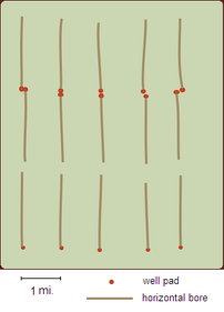 |
High density (Sanish field)  Medium density (Parshall field) 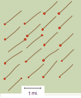 |
Horizontal hydraulic fracturing can result in fairly intensive development of large tracts of land. For example, a map in the March National Geographic, of a 50 x 90 mile area around Williston, North Dakota, USA, which overlies part of the Bakken tight oil formation, shows the locations of 3000 active oil wells. Almost no part of the 4500 square miles of oil bearing rock in the illustration is more than a mile from a horizontal bore. On the surface, it is virtually impossible to be more than 3 miles from a well pad.
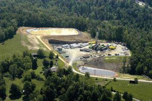
Well pads for horizontal hydraulic fracturing are usually 1½ - 2½ hectares in area.[44] More than one hole may be drilled from a pad; multiple-hole pads tend to be toward the large end of that area range.
Industry and government publications often claim that an advantage of horizontal hydraulic fracturing, compared to vertical drilling, is that the former reduces surface impacts because one horizontally drilled well generally reaches an area that it would take several vertical wells to exploit - the number of wellpads is thus reduced. Unfortunately, this is an argument against a straw man because the great majority of sites where horizontal hydraulic fracturing are used would not be developed at all with conventional vertical drilling. The choice that really presents itself is not horizontal fracking vs. vertical drilling; it is horizontal fracking vs. no drilling.[45]
Interzonal leakage of formation fluids
A potential problem with any petroleum well is that the vertical bore may provide a path for naturally occurring fluids in the rock formations to migrate from one level to another. This poses the risk of contamination of one stratum with fluids from another, one of the main concerns being contamination of soil and groundwater zones with oil, gas, saltwater (brine), or other fluids from below. (Saltwater is ubiquitous in petroleum-bearing geologies, believed to have been incorporated during the initial seabed accumulation of sediments.) The defence against interzonal leakage is provided by the casing and cementing of the well. Casing is tubing, almost always steel, inserted into the wellbore after drilling. To provide interzonal isolation, the space, called the annulus, between this tubing and the sides of the borehole must, further, be filled with cement; otherwise fluids could migrate up or down the annulus. The difficulty in filling an annulus a few centimetres thick but hundreds or thousands of metres long with cement, without gaps, and well-bonded to the casing and the sides of the borehole, is considerable, and the cement job is a frequent source of problems in petroleum wells.
“ Casing is run and cemented partly to protect the drilled hole from collapse, partly to isolate formations hydraulically, preventing flow of fluids from one horizon to another. Consequently, the integrity of the cement bond is of great importance.
Ideally, the cement should bond firmly to the casing itself and directly to the wall of the hole. A number of factors can prevent the attainment of a good cement bond:
- Eccentricity of casing. Casing clearances in the hole can be small, and eccentricity can lead to very small clearance areas where gelled mud can not be displaced by cement. This is a use for centralizers. ['Mud' is industry parlance for the fluid used to carry away cuttings during the drilling process: drilling fluid. - Communpedia ed.]
- Presence of mud cake. Across all porous permeable zones, a mud cake will exist. If this mud cake is not removed, the cement bond will be to mud cake, not to the formation. The tendency may be reduced by the use of scratchers, pre-wash, and operation in turbulent flow.
- Washed out hole. If the hole is washed out to excessive diameters, the cement may not fill the entire cross section. This is a factor to be considered while drilling and requires careful mud control and clay stabilizing muds in the drilling phase.
Additionally, after cementing, the excess pressure due to the difference in mud and cement density (cement is about 50% more dense than the average drilling mud) should be bled off. This prevents small contractions in the casing causing a rupture between cement and pipe. ” (Archer and Wall, Petroleum Engineering, pp 35-6.)
Another mechanism for bond separation is described by Waters and Beirute (1998). When the cement is semi-hardened, pressure from the weight of the cement can cause some of its fluids to go into the rock wall pores without the possibility of their volume being replaced by inflow of more cement. The result is cement shrinkage, and stress or breakage of the bond to wall or casing. In their words, the sequence is:
-gel strength development within the cement slurry
-pressure differential between initial hydrostatic pressure exerted by the cement column onto the gas-bearing formation and pore pressure of the formation
-fluid loss from the cement to adjacent formation
-volume losses during cement hydration reaction[46]
Cementing flaws in the annulus are hard to remedy once the cement has hardened.
It has long been known that a faulty cement job can lead to fluid migration:
Water migration was identified by Jones and Berdine (1940) as a problem resulting from incomplete displacement of drilling fluid filter cake during cement placement. Waters and Beirute (1998), p 251; they cite P H Jones and D Berdine, "Factors Influencing Bond Between Cement and Formation," API Drilling and Production Practice, 1940.
Concerning gas migration in the annulus, Waters and Beirute have written:
Flow may occurr almost immediately after cementing or may not begin until months after completion of the well. When flow has started, the migration problem becomes increasingly difficult to correct.[47]
The above statement raises the additional important issue of cement degradation over time. Even an initially sound cement job will not remain so forever. Nor can the steel casing be regarded as particularly durable in the saline environment.
Leaving aside the question of mechanical failure induced by high pressures during the hydraulic fracturing operation, cement is subject to a number of kinds of chemical degradation.
The resistance of concrete to attack by chemical agents is generally lower than to other forms of attack. (A M Neville, Properties of Concrete (1981), p 443.)
The more common forms of chemical attack are leaching out of cement, and action of sulphates, sea water, and natural slightly acidic waters. (ibid.)
Besides leaching, and exposure to waters containing sodium chloride (salt), acids, or sulphates, concrete is degraded by waters containing carbon dioxide or chlorides, and by "physical-chemical effects from internal phenomenon, such as alkali-aggregate reaction."[48] The mechanism of sulphate attack is described by Neville (1981):
Solid salts do not attack concrete, but when present in solution they can react with hardened cement paste. Some clays contain, for instance alkali, magnesium and calcium sulphate, and the groundwater in such clay is in effect a sulphate solution. Attack of cement can thus take place, the sulphate reacting with Ca(OH)2 and with calcium aluminate hydrate. The products of the reactions, gypsum and calcium sulphoaluminate, have a considerably greater volume than the compounds they replace, so that the reactions with the sulphates lead to expansion and disruption of the concrete.[49]
Although the binder, or paste, part of cement is attacked by acids, not alkalis, the "aggregate" (ie., the sand or gravel) may, depending on its composition, have the opposite suceptability, being attacked by alkalis in the paste or environment.[50]
Besides the concrete-degrading agents already mentioned, Neville lists some others: under "moderate" rate of attack are phosphoric acid, tannic acid, ammonium nitrate, bromine gas, and sulphate liquor; in the "slow" attack category are sodium hydroxide, sodium hypochlorite, sodium cyanide, chlorine gas, and soft water.[51]
An additional problem, recognised as one of the most serious durability problems with concrete structures above ground,[52] is corrosion of steel members imbedded in the concrete. All concrete has some permeability, therefore external moisture can eventually reach the steel and corrode it. The problem is worst in salty environments. The corrosion is "characterised by a disruptive expansion which accompanies the change of the iron into the corresponding oxides (rust)."[53] In other words, the steel expands and cracks the concrete. The problem has been most studied in structural concrete with imbedded steel "rebar", but the wellbore situation: steel casing contained by concrete annulus may be analogous. One factor favouring steel durability in underground placement, however, is that there may be an "insufficient supply of oxygen to support significant corrosion rates."[54]
The result of all of the above factors is that concrete is not a particularly durable material when viewed in the long term. An aspect of the problem easily visible to the average person is the 253,000 concrete bridge decks presently in "varying states of deterioration" in the United States.[55] The cost of their repair is estimated at $50 billion. M Collepardi, in a paper for the American Concrete Institute, characterises "ordinary durability" in aboveground concrete structures as a service life of 40-50 years. "Long term durability ... refers to a longer service life, with a minimum of 50 years up to 200 years and more."[56] There is less information about concrete durability underground; however, Gerwicke has stated:
Tremendous strides have been made in the understanding of durability in corrosive environments, yet it still remains the foremost problem facing structural concrete used today. We have only to look at the new Florida Keys bridge or at many other recent undersea tunnels to see that we don't yet have foolproof answers. Indeed at one time I thought of titling this talk - Tunnels in Trouble. The Kanmon tunnels between Honshu and Kyushu respectively [sic.] leak so badly that it affects not only the concrete tunnel liners but the rails and the running equipment. The Hong Kong tunnels were designed for a 120 year life and the concrete liners are in major disruption after only 4 to 10 years. The concrete in the Dubai tunnel (built in 1975) leaked so badly that the tunnel had to be completely repaired twice at a cost twice that of the original construction. The Suez tunnel reports similar difficulties .... The new dry dock at Abu Dhabi is reportedly also severely damaged.[57]
Commenting on the Gerwicke statement, civil engineer P Kumar Mehta states: "It should be emphasized here that around the world there are many 50-90 year old concrete structures still in good condition; [however], numerous cases of deterioration in recently built structures go unreported. Therefore, the above examples of concrete deterioration are not isolated examples."[58]
When considering the limits on durability of well casing and cementing, it should be remembered that the well holes themselves will typically remain in the rock formations on a geological time scale - hundreds of thousands or millions of years. If the casing or cementing is not extraordinarily durable, it must be envisioned that the well will become essentially an unlined hole at some time in the future. This raises issues of intergenerational ethics, eg., how much should the cost to some future generation of interzonal migration of fluids occurring during their lifetime be reckoned against the benefit to the present generation of obtaining fuel? It is also necessary to estimate probable rates, both of flow of pollutants, and of their dilution, eg., by recharging of aquifers with rainwater, over long periods of time. Episodic and discontinuous flows as well as long term averages must be considered.
Employment and economic development
The opening up of vast reserves of oil and gas that were previously unrecoverable has resulted in expanded opportunities for oil field workers in Texas, North Dakota, and the northern Appalachians as well as increased supplies of energy and export earnings in many countries.[59]
Fact check
Despite its prominent position on the Progressive agenda, the risks involved in fracking are limited in relationship to its economic utility.[60] Development of shale gas![]() in China is probably the only way in the short term to replace the massive pollution and addition to green house gasses resulting from coal-burning power plants.[61]
in China is probably the only way in the short term to replace the massive pollution and addition to green house gasses resulting from coal-burning power plants.[61]
The statement “There has never been a case of groundwater contamination as a result of hydraulic fracturing,” by Jack Gerard, president of the American Petroleum Institute is deceptive. There are numerous instances of groundwater contamination which have occurred during the drilling of wells, or later, during the long life of producing wells during which concrete casings may fail or due to misadventures with disposal of waste water. The statement is only accurate if it is limited to possible contamination which occurs directly from fracking while it is in progress. The geological formations being fracked are thousands of feet below the surface and are rarely hydrologically connected to ground water in a way that would result in contamination in a time frame of less then decades or centuries.[62] Research by the U.S. Department of Energy on one well in western Pennsylvania involving fracking fluid with chemical markers confirmed this.[63]
Notes
- ↑ "Frackers Are Losing $1.5 Billion Yearly to Leaks: Leaky pipes are the “super low-hanging fruit” of climate change" post by Tim McDonnell on Climate Desk April 5,
- ↑ "As Fracking Proliferates, So Do Wastewater Wells" article by Terrence Henry and Kate Galbraith in The New York Times March 28,
- ↑ "Parts of Low Country Are Now Quake Country" article by John Tagliabue in The New York Times March 26,
- ↑ Henry Fountain. "Study Links Quake to Technique at Oil Wells", March 28. Retrieved on March 29.
- ↑ Edwin Dobb, "America Strikes New Oil," National Geographic, March gives an example of 80%. Campbell and Horne give 98%.
- ↑ Warembourg et al (1990), p 368.
- ↑ De Witt (1986), p 4 or thereabouts.
- ↑ Alexander et al, p 8.
- ↑ Alexander et al, p 8.
- ↑ Alexander et al p 7.
- ↑ De Witt (1986), p 4.
- ↑ Best; Dobb.
- ↑ De Witt (1986), p 4.
- ↑ US EIA "FAQ"s.
- ↑ "As with shale gas, the application of horizontal drilling and hydraulic fracturing significantly increases the development of tight oil resources." AEOEarly Release Overview, US Energy Information Administration, Dec. Relates to report number DOE/EIA-0380ER(2013). The production forecast is also from the Overview.
- ↑ US Dept. of Energy, Primer, p 15.
- ↑ Aguilera et al.. They are also good on the definition.
- ↑ Ibid.
- ↑ Technically Recoverable Shale Oil and Shale Gas Resources: An Assessment of 137 Shale Formations in 41 Countries Outside the United States. (PDF) U.S. Energy Information Administration (EIA). URL accessed on June 11.
- ↑ Alexander et al., p 11 or thereabouts.
- ↑ Oil Independents, "Oil and Gas 'Reserves' - Definitions Matter".
- ↑ U.S. Energy Information Administration U.S. Crude Oil, Natural Gas, and NG Liquids Proved Reserves, August edition; and U.S. EIA, Today in Energy, 20 July.
- ↑ "While discoveries of new fields and reservoirs are important indicators of new resources, they generally comprise a small percentage of overall reserve additions on an annual basis. Revisions occur primarily when operators change their estimates of what they will be able to produce from the properties they operate using existing technology and prices." U.S. EIA U.S. Crude Oil, Natural Gas, and NG Liquids Proved Reserves, August edition. Also, U.S. EIA, Today in Energy, 20 July.
- ↑ Nick Snow, Feb.
- ↑ Christopher Helman "Meet the Oil Shale Eighty Times Bigger than the Bakken", Forbes, 06/04/2012, estimates, by a very rough-and-ready method, 1,900 billion barrels recoverable from the Bazhenov shale. RT news (TV-Novosti), "Gazprom joins shale race", 26 Jan says one company, Gazprom Neft, announced that it expects to get a cumulative amount of at least 150 million tons (about 1.1 billion barrels) from the Bazhenoz. Then they say that geologist Ivan Nesterov thinks there may be 100 billion tons (about 730 billion bbl) there; is that in-place or recoverable? they don't say.
both retrieved April. - ↑
Nadia Rodova (Moscow), "Russian Oil Developments" >> "Will Russia replicate US success in tight oil development?", Platts, August 23,: "As Russia's traditional oil provinces such as West Siberia are depleting, the country is increasingly looking to more expensive new frontier resources.... The national subsoil agency Rosnedra estimates that the most promising reserves of tight oil, the Bazhenov formation in West Siberia, may hold between 25 billion mt (182 billion barrels) and 50 billion mt of recoverable reserves.
"Output from Bazhenov could provide between 800,000 b/d and 2 million b/d by or up to nearly one-fifth of the country's current total production of just over 10.2 million b/d, Russia's energy ministry estimates.
"But at present tight oil reserves account for no more than 400,000 b/d, or around 4% of total Russian oil output, as oil producers are continuing to test costly and difficult geological plays to find the most efficient oil production techniques.... "The Bazhenov formation, like the similar Achimov and Tyumen formations, is below conventional oil layers, differs from them by geological composition, and is challenging due to narrow pay-zones and low permeability.
"But perhaps the most formidable challenges are an extremely low recovery rate as well as high decline rates that translate into a high lifting cost.... At present, recovery rates at different tight oil projects in Russia are just at between 2% and 8%, according to Lukoil which estimates that tight oil reserves in the country amount to as much as 62% of its total reserves.
"Lifting costs of tight oil are estimated at between $14/b and $40/b, according to data by different companies.
"In comparison, the lifting cost of some new conventional oil projects in Russia exceeds $10/b, while average lifting costs are much lower and stood at below $3/b for Rosneft and $5/b for Lukoil, according to Q2 financial reports of the two biggest oil producers in Russia.
"While developing the Bazhenov formation has so far been unprofitable, recent success in developing tight oil reserves in the US is expected to give an impetus to the development of tight oil reserves elsewhere in the world, including Russia." - ↑ Page 221.
- ↑ EIA, World Shale Gas Resources.
- ↑ Alexander et al; Campbell and Horne say 8-26.5 M litres, but occasionally as high as 90 M litres (p 2); Al et al say 20-60 M litres.
- ↑ Mooney, p 85.
- ↑ Alexander et al, p 10.
- ↑ Valko et al. (1998), p 487-8.
- ↑ Rheology: the science of deformation and flow of materials.
- ↑ Valko et al. (1998), p 488.
- ↑ "Gelling agent, crosslinker, and pH control (buffer) materials define the specific fluid type and are not considered additives. Fluid additives are materials used to produce a specific effect independent of fluid type." - Valko et al (1998), p 488.
- ↑ Valko et al (1998), p 488.
- ↑ Ibid, pp 488-9.
- ↑ Valko et al (1998), p 489.
- ↑ Valko et al (1998), p 489.
- ↑ Results cited in Joshi (1991), pp 347-8.
- ↑ Gray (1995), p 204.
- ↑ Sumi.
- ↑ U.S. EIA Annual Energy Outlook, p 58.
- ↑ Alexander et al.
- ↑ Eg, Alexander et al. make the fallacious comparison.
- ↑ Waters and Beirute (1998), p 253.
- ↑ Waters and Beirute (1998), p 251.
- ↑ Mehta (1991), p 3.
- ↑ A M Neville, p 445.
- ↑ Mehta, pp 7-8.
- ↑ Neville (1981), Table 76, "Effect of Some Commonly Used Chemicals on Concrete." He also has a "negligible" rate of attack category, and a "fast" category.
- ↑ Mehta, p 3.
- ↑ M Collepardi in Malhotra, p 35.
- ↑ Goodfellow, p 9.
- ↑ Mehta (1991), p 2.
- ↑ M Collepardi, p 3.
- ↑ Qouted in Mehta (1991), p 3.
- ↑ Mehta (1991), p 3.
- ↑ Kate Galbraith. "Ready (or Not?) for a Great Coming Shale Boom", April 27. Retrieved on April 28.
- ↑ "The Facts on Fracking" opinion by Susan L. Brantley and Anna Meyendorff in The New York Times March 13,
- ↑ "China Must Exploit Its Shale Gas" op-ed by Elizabeth Muller of Berkeley Earth in The New York Times April 12,
- ↑ "Drillers Silence Fracking Claims With Sealed Settlements" article by Jim Efstathiou Jr. and Mark Drajem on Bloomberg News 5,
- ↑ "DOE Study: Fracking Chemicals Didn't Taint Water" Associated Press July 19,
Bibliography
Robert Aguilera, Thomas Harding, and Frederico Krause, "." 19th World Petroleum Congress, Spain.
Matthew D Alexander, Lining Quan, and Tim A Ryan, Considerations for Responsible Gas Development of the Frederick Brook Shale in New Brunswick. Fundy Engineering and Atlantic Centre for Energy; Saint John, New Brunswick, Canada;.
Moujahed Al-Husseini, "," Geo Arabia, vol 14 no 1, pp 215-267.
J S Archer and P G Wall, Petroleum Engineering. Graham and Trottman; London, England; (1986).
Alan Best, "Colorado Counties Consider Drilling's Impacts to Roads," Planning, Aug/Sep p 6.
Tom Daniels, "Drilling Down on Hydrofracking," Planning, Aug/Sep p 33.
Karen Campbell and Matt Horne, Shale Gas in British Columbia: Risks to B.C.'s water resources. Pembina Institute for Appropriate Development; Drayton Valley, Alberta, Canada;. (ebook)
M Collepardi, "Ordinary and long-term durability of reinforced concrete structures," in V M Malhotra (ed.), Proceedings of the Fifth International Conference of the American Concrete Institute Vol. 1. Farmington Hills, Michigan, USA;.
Wallace De Witt Jr., "Devonian Gas-Bearing Shales in the Appalachian Basin," in Charles Spencer and Richard Mast (ed's) Geology of Tight Gas Reserves, American Association of Petroleum Geologists, 1986.
Edwin Dobb, "America Strikes New Oil", National Geographic, March.
Michael Economides, Shari Dunn-Norman, and Larry Waters, Petroleum Well Construction, John Wiley and Sons; Chichester, West Sussex, England; 1998.
Robert Goodfellow, Concrete for Underground Structures: Guidelines for Design and Construction..
Forest Gray, Petroleum Production in Nontechnical Language. Penn Well Books; Tulsa, Oklahoma, USA; 1995.
Sada D Joshi, Horizontal Well Technology. Penn Well Books; Tulsa, Oklahoma, USA; 1991.
P K Mehta, "Durability of Concrete: Fifty Years of Progress?" in V M Malhotra, ed., Durability of Concrete. American Concrete Institute; Detroit, Michigan, USA; 1991.
Chris Mooney, "The Truth About Fracking," Scientific American, November.
A M Neville, Properties of Concrete, 3rd edition. Pittman; London England; 1981.
Oil Independents, Oil and Gas "Reserves" - Definitions Matter.
Brian Skinner, Earth Resources. Prentiss-Hall ; Englewood Cliffs, New Jersey, USA ; .
Vaclav Smil, Energies. MIT Press; Cambridge, Massachussetts, USA ; .
Lisa Sumi, Environmental concerns and regulator initiatives related to hydraulic fracturing in shale gas formations: potential implications for North American gas supply. Council of Canadians,.
United States Department of Energy, "Modern Shale Gas Development in the United States: A Primer. April.
United States Energy Information Administration, . Especialy "Issues in focus" >> 11. "U.S. crude oil and natural gas resource uncertainty" (pp 56 ff.).
United States Energy Information Administration, Frequently Asked Questions >> "Does EIA have data on shale (or "tight") oil production?"
United States Energy Information Administration, World Shale Gas Resources: An Initial Assesment of 14 Regions Outside the United States, April.
United States Energy Information Administration , Today in Energy, 20 July.
United States Energy Information Administration, U.S Crude Oil, Natural Gas, and NG Liquids Proved Reserves, August. retrieved April.
Peter Valko (Texas A&M University), Lewis Norman (Halliburton Energy Services), and Ali Daneshy (Halliburton Energy Services), Chap. 17, "Well Stimulation", in Economides et al., 1998.
P A Warembourg et al, "Fracture Stimulation Design and Evaluation", in Society of Petroleum Engineers, Hydraulic Fracturing - 2. Soc. of Petr. Engineers; Richardson, Texas, USA; 1990. Pp 360-71.
Larry Waters and Robert Beirute, "Formation-fluid Migration After Cementing," in Economides et al. (1998)
External links and further reading
- "Center created to set Pennsylvania shale-drilling standards" Philly March 20,
- "HYDRAULIC FRACTURING: White House huddled with industry before changes to BLM fracking rule" Mike Soraghan, E&E reporter EnergyWire: Friday, April 12,
- "Fracking Can Be Done Safely, but Will It Be?"
- "Fracking films reflect twists in drilling debate" article by Kevin Begos, Associated Press July 22,